01
Induce Charge
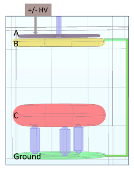
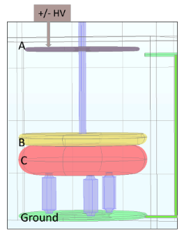
Input electrode A is biased by the external high-voltage supply. Transfer electrode B begins close to A while connected to ground, allowing capacitive induction to load charge onto B.
Development of an in-situ electrostatic multiplier intended to generate hundreds of kilovolts inside the cryogenic nEDM@SNS apparatus while avoiding the challenges of a conventional full-voltage cryogenic feedthrough.
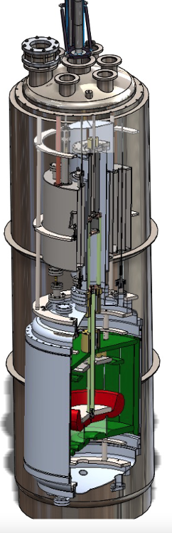
The nEDM@SNS experiment requires several hundred kilovolts on a measurement-cell electrode immersed in approximately 0.4 K liquid helium. Delivering the full voltage through a conventional feedthrough creates difficult thermal, electrical, magnetic-material and physical-size constraints.
The Cavallo multiplier approaches the problem differently: bring a much smaller voltage into the cryogenic region, then repeatedly transfer electrostatically induced charge to an isolated collector electrode. The construction-ready design targets approximately 650 kV from a 50 kV input.
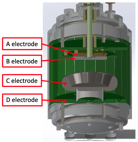
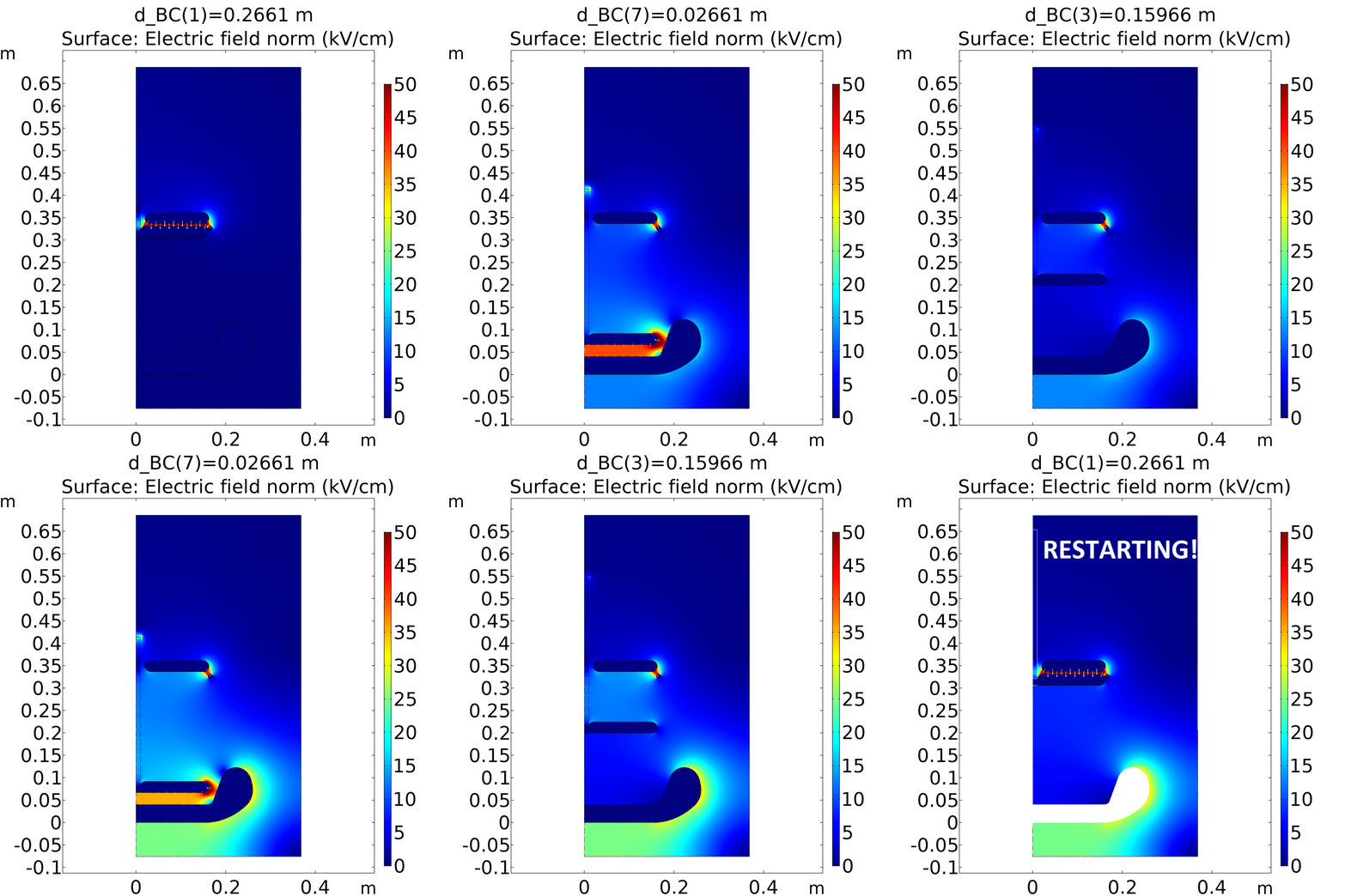
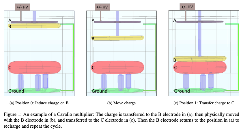
The multiplier builds voltage through repeated mechanical charge-transfer cycles rather than directly feeding the final high voltage into the cryostat.
Input electrode A is biased by the external high-voltage supply. Transfer electrode B begins close to A while connected to ground, allowing capacitive induction to load charge onto B.
B disconnects from ground while retaining its charge. A mechanical actuator translates the electrode away from A and toward the isolated high-voltage collector C.
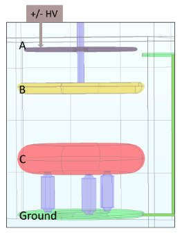
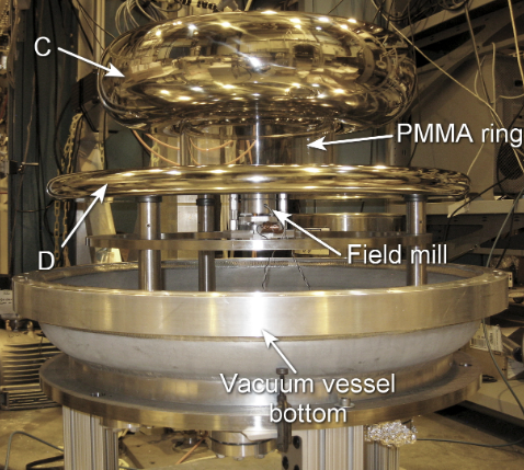
B approaches C and transfers charge to the isolated collector. B then returns to its starting position and the cycle repeats, progressively raising C to a much larger potential.
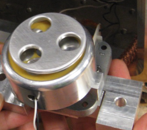
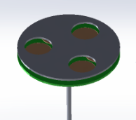
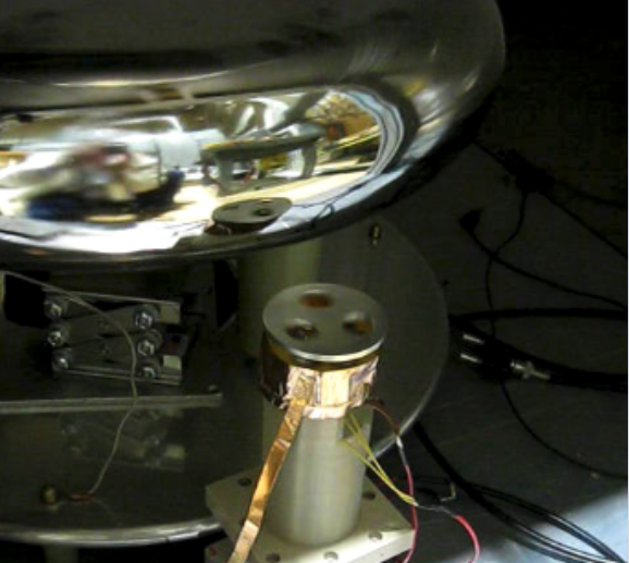
The collaboration used a custom rotary field mill to infer the high-voltage collector potential without making a direct electrical measurement at hundreds of kilovolts. A grounded rotating shutter periodically exposes a sensing electrode to the electric field, converting the static field into an AC signal that can be calibrated against known collector voltage.
Role distinction: I did not design or develop the field mill. I supported the larger apparatus, vacuum/cryogenic infrastructure and testing environment in which the HV system and its diagnostics operated.
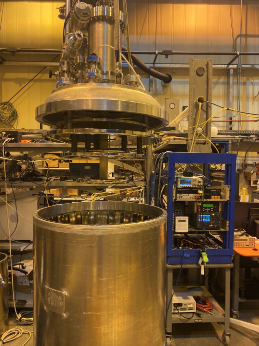
I built most of the supporting test apparatus around the central Cavallo high-voltage volume: the cryogenic and vacuum infrastructure, plumbing, support hardware, instrumentation, DAQ interfaces, utilities and test setup required to install the central assembly and operate the system.
Once the supporting systems were commissioned and operating, I handed the apparatus over for experimental operation while continuing daily checks of cryogenic, vacuum and instrumentation behavior.
My contribution was concentrated on the infrastructure and integration required to make the Cavallo central volume a functioning experiment: fabrication, cryogenics, vacuum, instrumentation, utilities, mechanical handling, work control and operational support.
I fabricated much of the hardware connecting the central Cavallo volume to the surrounding test system. This included extensive 316 stainless-steel tubing work from small instrumentation lines through larger cryogenic/exhaust plumbing, plus support structures and practical installation hardware.
I bent, fitted and welded tubing and verified components with vacuum, leak and cryogenic tests before integrating them into larger subsystems.
I outfitted the apparatus with the cryogenic and vacuum instrumentation needed for commissioning and operation. The DAQ/instrumentation package was adapted from the earlier MSHV experiment, then tested as an integrated system.
The system included roughing and turbo pumping, leak-checker interfaces, vacuum gauges, temperature and pressure sensors, liquid-level measurement, fill-valve automation and organized electronics/wiring. I calibrated the custom liquid-level sensor and verified the instrumentation and DAQ together before operation.
I provided crane and mechanical-handling support to place the HV central volume into the dewar, then connected the cryogenic plumbing and instrumentation to the surrounding system. Leak checking was iterative: individual components, assembled subsystems and finally the complete apparatus were tested as the build progressed.
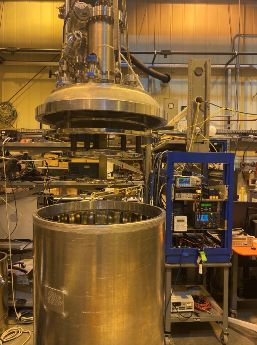
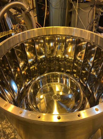
Before cryogenic operation, the full-scale system was demonstrated at room temperature in SF₆. I served as the SF₆ gas owner/support contact, supplied the gas system and provided vacuum and leak-checking support for the HV tests.
The published full-scale demonstration reached approximately 255 kV from a 25 kV input in about 600 Torr SF₆. I am a coauthor on the 2026 paper reporting this result.
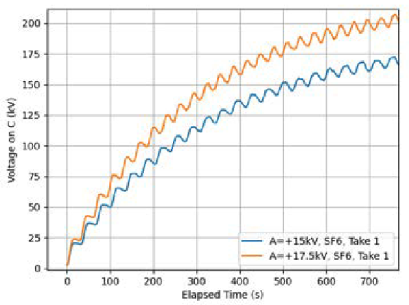
Published full-scale room-temperature demonstration in approximately 600 Torr SF₆.
The original apparatus was built for a full liquid-helium test configuration. When program priorities and helium availability changed, the cryogenic test was simplified to liquid nitrogen. I rebuilt internal portions of the dewar and exterior plumbing to the second configuration, working closely with the responsible engineer to install the revised system.
I also worked with engineering on the formal LN₂ startup/test procedures and represented the cryogenic-handling side of the apparatus during electrical, pressure, cryogenic and industrial-hygiene walkdowns under the IWD.
The cryogenic plumbing, vacuum systems, instrumentation and supporting infrastructure operated as intended, and I brought the system to the point where the experiment team could run it. I then handed the apparatus over for experimental operation while checking in daily and observing system behavior.
During LN₂ testing, the team encountered difficulty maintaining the stable pressure needed for the measurement because the dewar top and vessel—hardware inherited from two different projects—did not mate perfectly. The program was subsequently curtailed before that configuration produced the intended cryogenic dataset. I would describe that outcome carefully: the supporting systems I owned were commissioned and operational, while the remaining experimental limitation was associated with the inherited vessel interface and the program ended before a further redesign could be completed.
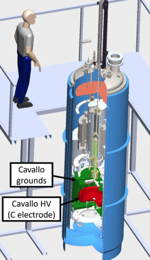
The 2026 full-scale Cavallo paper reports the room-temperature SF₆ demonstration and includes me, T. J. Schaub, as a coauthor.
Demonstration of 255-kV high-voltage generation with a Cavallo multiplier system ↗
The 2026 Physical Review C paper documents the broader cryogenic high-voltage and electrode development program for nEDM@SNS and includes me as a coauthor.
A 2023 APS/DNP-JPS presentation documents preparation for the cryogenic test of the full-scale multiplier and includes me among the project authors.