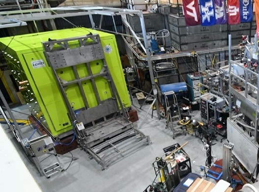
Real experimental-area photograph cropped from released LANL nEDM / Area B imagery. The bright green structure is the magnetically shielded room housing the core nEDM measurement region.
What is the experiment?
Searching for a tiny electric dipole moment in the neutron
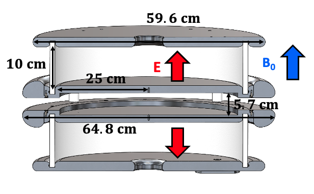
The experiment stores polarized ultracold neutrons in measurement chambers and observes their spin precession in carefully controlled magnetic and electric fields. The measurement searches for an extremely small change in precession associated with reversing the electric field.
A nonzero neutron electric dipole moment would be evidence of physics beyond the Standard Model and is connected to the broader question of why the observable universe contains much more matter than antimatter.
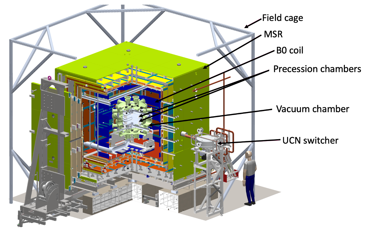
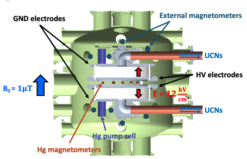
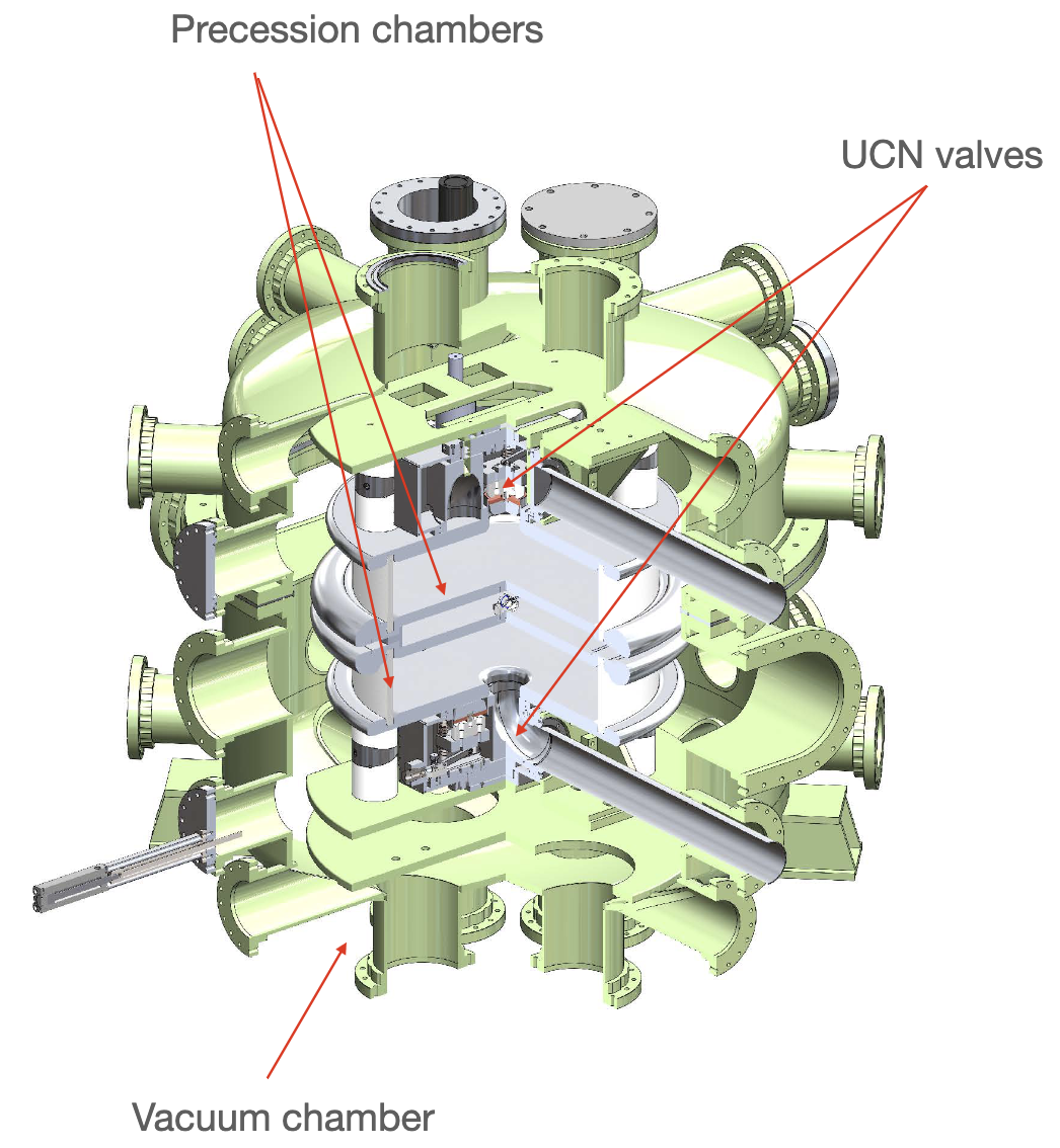
Full apparatus context: field cage, magnetic shielding, B0 coil, precession chambers, vacuum chamber and UCN transport hardware.
How nEDM works
How the LANL nEDM Experiment Works
The experiment searches for a permanent neutron electric dipole moment by measuring an extremely small electric-field-dependent shift in the spin-precession frequency of stored ultracold neutrons.
01
Produce & Polarize UCN
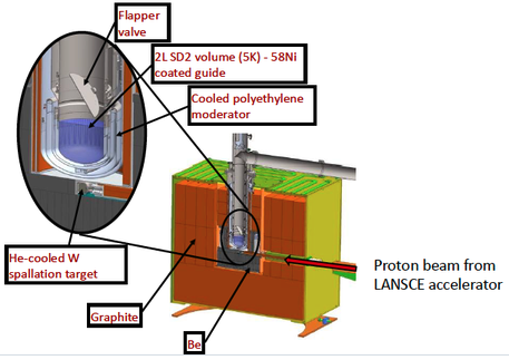
An 800 MeV proton beam produces spallation neutrons in a tungsten target. Moderation and a cryogenic solid-deuterium converter reduce their energy to the ultracold regime. The UCN are transported through guides and polarized before entering the nEDM apparatus.
02
Store & Measure Spin Precession
Polarized UCN are stored in two precession chambers inside a precisely controlled magnetic environment. Ramsey's method uses two RF spin rotations separated by a long free-precession period while electric and magnetic fields are applied. A neutron EDM would appear as a small electric-field-correlated change in precession frequency.
03
Compare Fields & Control Systematics
The double-cell geometry and repeated field configurations allow the experiment to compare neutron precession while controlling magnetic-field effects. Mercury-199 co-magnetometry and external magnetometers track the magnetic environment, while screened low-magnetic-signature components reduce gradients near the measurement cells.
My role
Building and commissioning the hardware that stores and controls the neutrons
My work centered on the main vacuum vessel and neutron-valve system: mechanical construction and integration, vacuum preparation, hydraulic actuation, pressure and position instrumentation, first-generation controls, installation and troubleshooting during commissioning.
Build-to-commissioning progression
From vacuum preparation to an installed neutron-valve system
The sequence below follows the actual development path: initial vacuum conditioning, valve construction and component preparation, magnetic-material screening, two generations of hydraulic actuation and controls, alignment and integrated vacuum testing, endurance testing, installation and later field repair.
Stage01
Initial vacuum preparation & conditioning
The work began with the main G10 components installed in the chamber and an extended vacuum-conditioning period. I rough-pumped the system for several weeks and then transitioned to turbomolecular pumping for several more weeks before the chamber was opened again for valve-system development.
Pump-down included leak checking to identify and resolve leaks rather than relying on pressure alone. This established the vacuum behavior of the large custom vessel and began the long process of reducing outgassing before the more complex mechanical hardware was integrated.
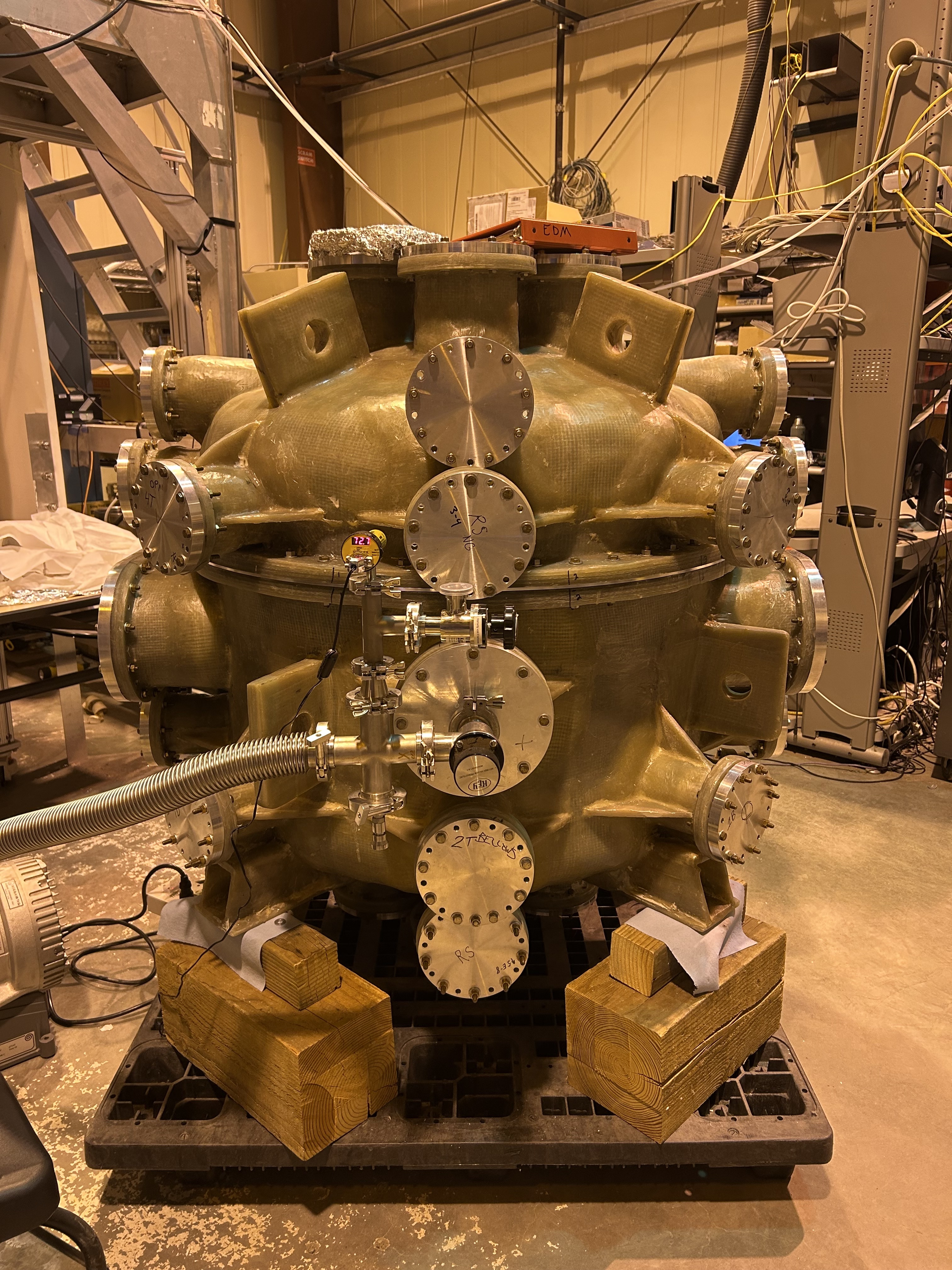
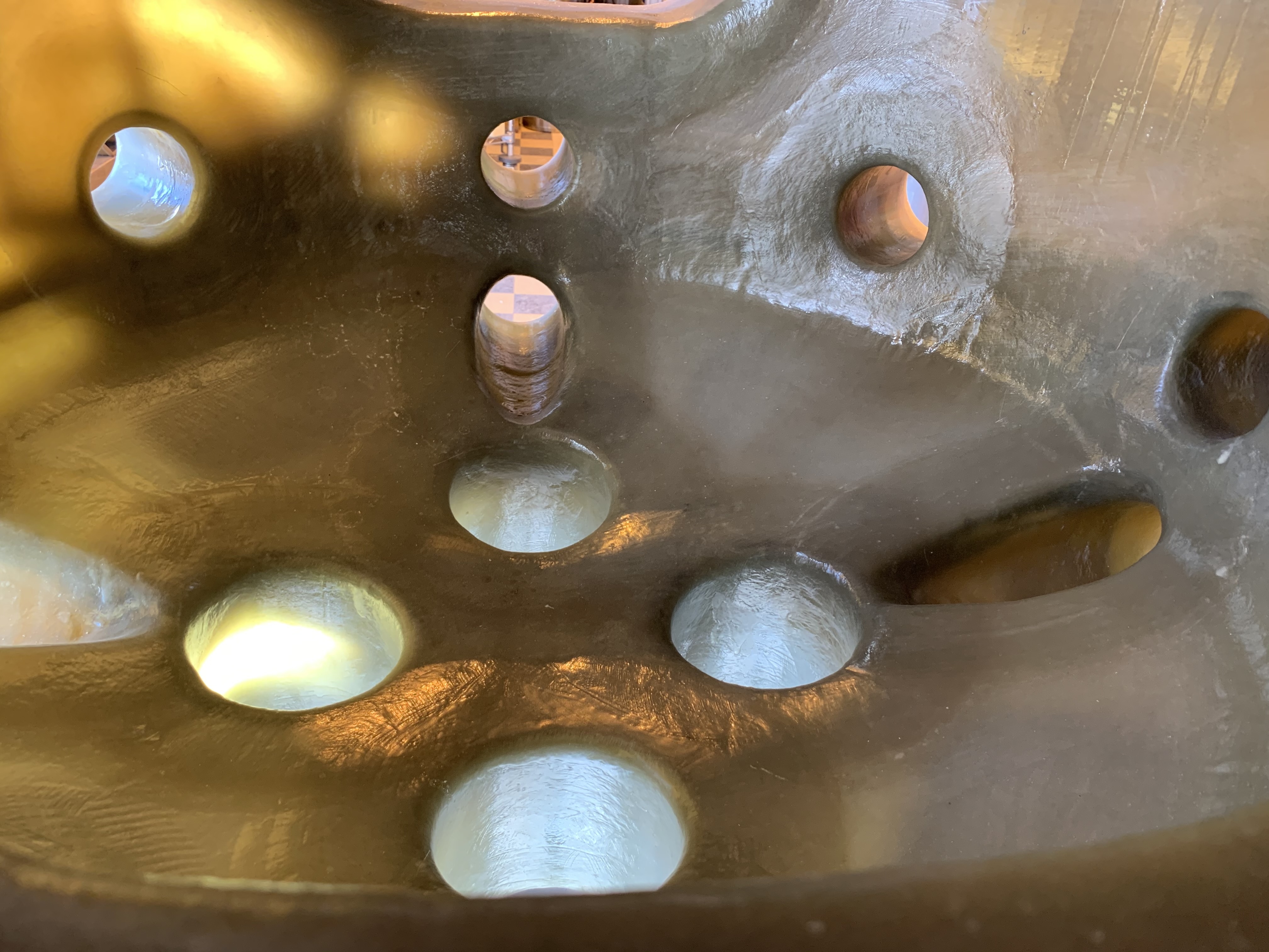
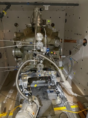
Main chamber during vacuum preparation.Interior of vacuum chamber.
Stage02
Valve construction, cleaning & mechanical development
After the initial vacuum conditioning, the chamber was opened for an extended period while I built up and hand-tested the two neutron valves. I first concentrated on getting the bottom valve operating smoothly by hand before adding powered actuation.
Component preparation was continuous throughout this work. Parts were carefully cleaned before installation and often cleaned again after rework or handling. Depending on the material and component, this included non-abrasive cleaning, ultrasonic cleaning, isopropyl alcohol and deionized water. Metal hardware could receive a detergent or Citranox bath, followed by extended oven baking and a final alcohol / deionized-water cleaning before returning to the apparatus.
The assembled system required repeated mechanical adjustment. Bringing both the upper and lower cells into alignment while also mating correctly to the neutron beam guides and maintaining the vacuum interfaces became a major part of the development work.
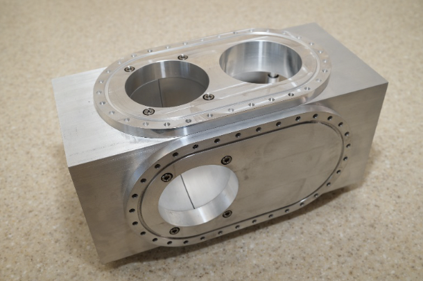
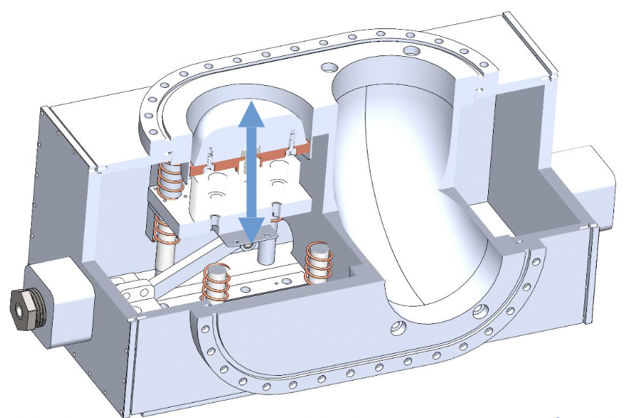
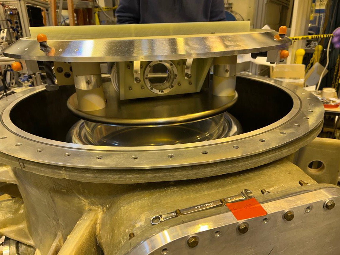
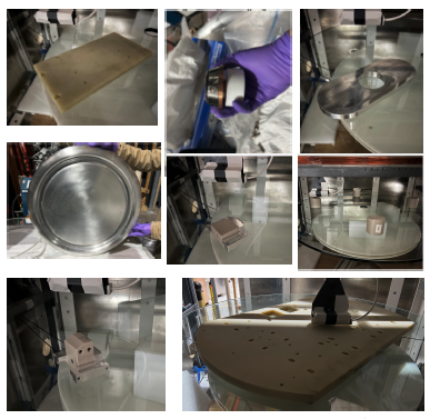
Machined chamber hardware used in the precession-cell assembly.Central-assembly context showing the two precession chambers, UCN valves and surrounding vacuum chamber.Cutaway view of the chamber hardware and valve-motion geometry used during mechanical development.Valve and chamber hardware during mechanical fit-up in the open vacuum vessel.
Stage03
Magnetic-material screening before integration
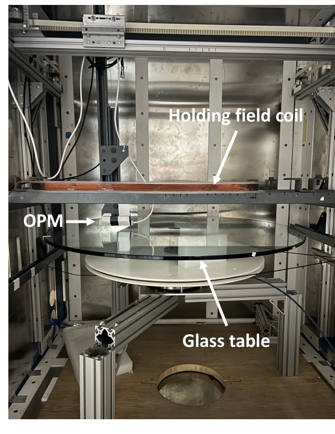
Because the measurement cells had to operate in an extremely controlled magnetic environment, candidate hardware was also screened for magnetic impurities before final integration. The project used a dedicated magnetic-impurity scanner and evaluated more than 100 parts, including valve hardware, guides, sealing components, chamber supports, fasteners, actuators and other pieces used around the central assembly.
My role was on the hardware side rather than the magnetic measurement or analysis. I disassembled the cell hardware, prepared and cleaned parts, delivered components for scanning, helped with mechanical aspects of the scanner / turntable when needed, and later reassembled the apparatus. The physicists performing the measurements and simulations determined the relevant magnetic limits for a component's location.
If a component produced an unacceptable result, I was brought into the practical redesign discussion: whether the solution should be a different material, geometry, fabrication route or replacement component. Cleaning could also be repeated when contamination or residue was suspected.
Turntable magnetic-impurity scanner used to evaluate components before integration.Central-assembly components during construction, preparation and fit-up.
Stage04
First hydraulic concept: stepper-driven actuation
The first powered concept used a stepper motor to drive a hydraulic piston. The goal was precise, controlled displacement, and I built a separate DAQ and GUI around this configuration for testing and operation.
Long-duration testing exposed a problem that was not obvious from the concept alone: small hydraulic blowby at the chamber piston accumulated over repeated motion. Over time, the chamber-side piston could drift outside the usable stroke of the stepper-driven piston. Precision at the drive end therefore did not guarantee reliable position authority over long-term operation.
Design iteration: the stepper-based system was useful development hardware even though it was not retained. Testing revealed a cumulative hydraulic behavior that drove the actuation concept toward a continuously available pressure source.
Stage05
Revised hydraulic system & new controls
I then built out the revised system around a hydraulic pump so drive pressure would be available whenever valve motion was required. I designed and built a custom electrical interface box that acquired four pressure signals and two valve-position signals, controlled four relays, and connected the hydraulic hardware to a live-view plotting GUI.
The GUI displayed valve position and pressures through each stroke and provided useful troubleshooting messages when a protection condition tripped. Raw position information was also made available for inclusion in the experiment DAQ stream.
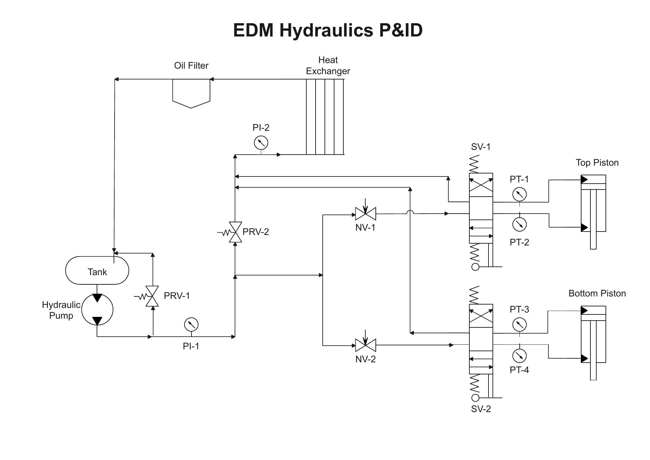
I documented the hydraulic system with the working P&ID shown below and developed a bill of materials with vendor data sheets for the hydraulic components. Official pressure-safety calculations were provided by Design Engineering; I reviewed the system from the build and operating side and supported its approval, but I was not the design authority responsible for those calculations. The final operating behavior was tuned experimentally rather than through a detailed analytical model. Needle valves NV-1 and NV-2 were used to control flow to the pistons while retaining higher available hydraulic pressure. I consulted with the physicists on the desired valve stroke time and tuned the system to achieve a reliable operating stroke.
The system required additional mechanical tuning as the valves were brought into reliable operation. Once the lower cell was operating smoothly, getting the upper and lower assemblies to work together required significant realignment and repeated teardown and rebuild of the apparatus. High voltage was not part of this test configuration; the system did not yet include the HV feedthroughs.
Working hydraulic-system P&ID developed during integration and commissioning. Working system documentation; not an issued engineering drawing.
Stage06
Integrated alignment, vacuum & endurance testing
Final mechanical alignment had to satisfy several requirements at once: both valves needed smooth travel, the cells had to mate correctly with the neutron beam guides, and the assembled chamber had to maintain high vacuum. The apparatus was repeatedly adjusted, pumped down and retested.
Vacuum loading produced small shifts in the structure, so support alignment was adjusted after observing the system under vacuum rather than relying only on atmospheric-pressure fit-up. After the final configuration was established, I performed the proof test under vacuum, cycling the valve system thousands of times before installation.
Why the endurance test mattered: the goal was no longer simply to demonstrate that a valve could move. The complete mechanical, hydraulic, vacuum, instrumentation and control system had to continue operating repeatedly in its integrated configuration.
Stage07
Magnetic shield room door alignment & troubleshooting
I worked closely with Magnetic Shield Corporation on alignment and maintenance of the large magnetic-shield-room door surrounding the nEDM apparatus. I installed an extended door-track upgrade, cleaned and aligned electrical contact points, and performed resistance and continuity checks across the door interface.
I also troubleshot a mechanical latching issue in which cam mechanisms were hanging up before full engagement, preventing the door from closing and sealing properly. I iteratively adjusted the door and latching system to support reliable opening, closing, electrical contact and mechanical engagement.
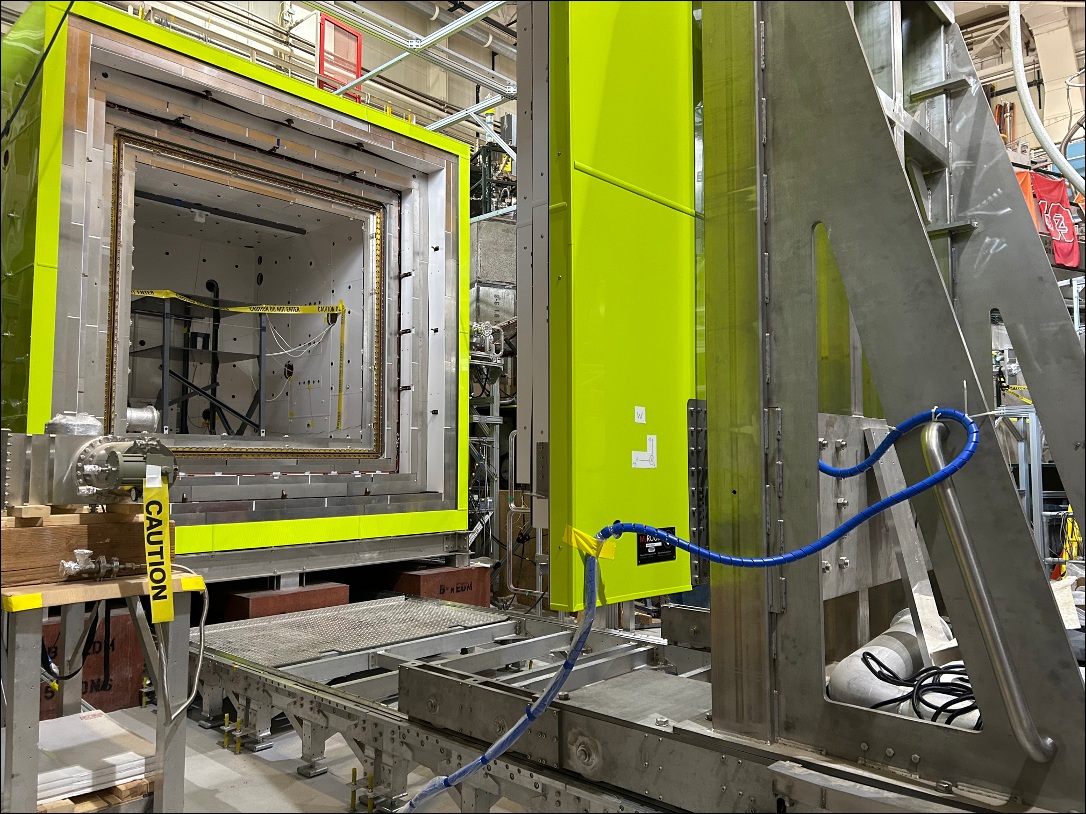
Magnetic shield room door and track system surrounding the nEDM apparatus.
Stage08
nEDM installation & coupling to the UCN beamline
Installation required more than lifting the chamber into place. A separate platform was installed at the opening of the nEDM magnetic-shield room, and the chamber was placed on a custom trolley so the assembled vessel could be rolled into position and connected to the neutron beamline.
Chamber installed in the experimental area with vacuum and instrumentation connections.
Stage09
Commissioning troubleshooting & field repair
Commissioning included both controls faults and mechanical problems. In one case, a valve repeatedly stopped partway through its travel. Pressure, position and control-state information showed that the system was reaching a protective pressure threshold rather than simply binding mechanically; correcting the threshold and retesting restored continuous motion.
A more difficult problem appeared after the apparatus had already been installed. Loose internal hardware interfered with valve travel. Repair required disconnecting the integrated system, rolling the chamber back out of the magnetic-shield-room opening on the trolley, opening the vessel in the beam area, disassembling the cell hardware, correcting the problem and completely reassembling the chamber.
Lesson carried forward: inaccessible internal hardware needs objective verification before final integration. Once a complex system is installed, a small assembly problem can become a major disassembly, access and reassembly effort.
Project resolution: the assembly was completed in time to take beam. The experiment demonstrated that ultracold neutrons could be captured, stored and dumped using both cells, completing the proof-of-concept objective for this stage of the apparatus.
Publication note
Related neutron-EDM publication record
I am a coauthor on the 2026 high-voltage and electrode-system paper for the separate cryogenic nEDM@SNS program. Because this page documents the LANL room-temperature/vacuum nEDM apparatus, I do not present the nEDM@SNS paper here as a publication from this project. It is listed on the Cavallo Cryo & HV page and on the Publications page.